|
XI'AN KINGWELL OILFIELD MACHINERY CO.,LTD
|
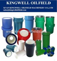
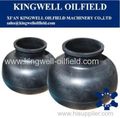
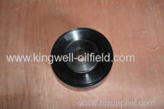
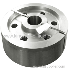
OEM interchangeable mud pump spare parts
| Price: | 100.0 USD |
| Payment Terms: | T/T,WU |
| Place of Origin: | Shaanxi, China (Mainland) |
|
|
|
| Add to My Favorites | |
| HiSupplier Escrow |
Product Detail
1. forged alloy steel
2. OEM interchangeable
3. API standard
4. Small MOQ accepted
5. Stocks available
6. Quick delivery
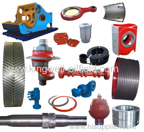
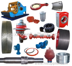
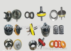
Main spare parts Kingwell are able to supply:
1. Features of power end:
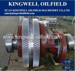
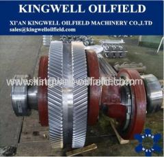
1).The crank shafts are driven by herring bone gear without tooling with drawal groove.
2). Crank shafts are made of alloy steel .
3). Cross head guiding plates are changeable .
4).·Framesare of high strength , supreme rigitidy and light weight for the adoption of welded steel plate parts .
5). The extention rod adopts double dealing structure with excellent sealing effect.
6). The combination of the forced lubrication and splash lubrication applied for the power end.
2. Stand
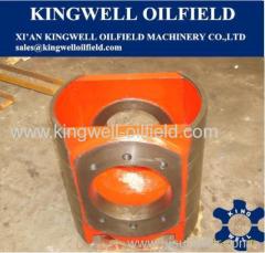
The stand is made of welded steel plate with stress relief, which leads to excellent rigidity and high strength. The reinforcing plate structure is applied forstiffness at the crank shaft bearings. Necessary oil reservoir and oil routesystem are set up inside the stand aiming at cooling and lubrication.
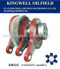
3. Crankshaft
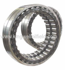
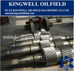
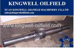
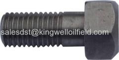
The crank shafts are alloy steel castings. Gears, connection rods and bearings areseparatelymounted on the crank shaft. The teeth on the gears are herringboneteeth. The tight fitting is used for the assemble between inner hole of gearsand crank shaft together with inserting bolt and locknut for solidification. Thebig end of rod is installed respectively on three eccentric elbow of the crankshaft by means of the single column roller bearing, while the small end isinstalled on the cross pin through the double column roller bearing. Both endsof the crank shaft are double column centripetal sphere roller bearing.
4. Pinion shaft
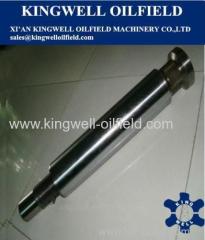
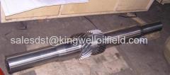
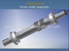
The pinion shaft are alloy steel forgings assembling with manufactured herringboneteeth gear featured with medium-hardnessed teeth surface. For the convenience ofmaintenance, the single column centripetal long roller bearing is selected forthe internal circle without cover edge. Either end of the shaft can be mountedwith belt wheel or sprocket wheel.
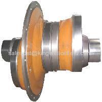
5. Crosshead and extension rod
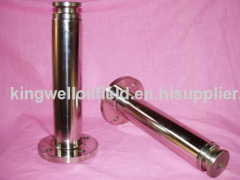
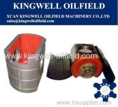
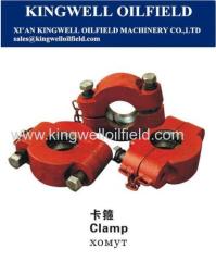
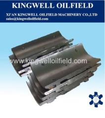
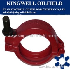
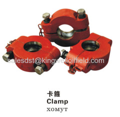
Thematerials of the crosshead and the crosshead guiding plate are of outstandingwearing resistance with long service life. By the adoption of upper and lowerguiding plates, the concentricity is in a position to be adjusted by employingshims at the lower guiding plate. The crosshead and the intermediate rod areconnected by flange bolt, with which rigid connection the concentricity betweenthe rod and the crosshead can be guaranteed. Clamps in light weight areemployedfor connection between extension rod and piston rod , which areconvenient and reliable .
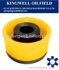
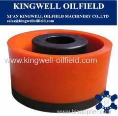
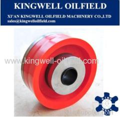
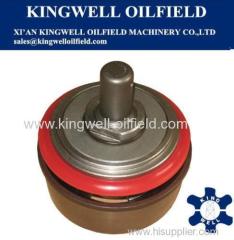
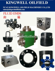
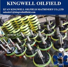
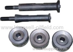
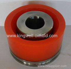
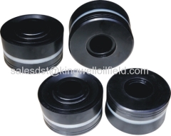
Hydraulic cylinders, valveassembly , liners and pistons are the major components of the fluid end.
6. Features of hydraulic end:
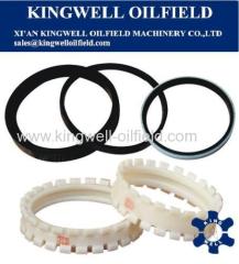
1).Sealingparts are impacted in rigid with good sealing.
2).Uprighthydraulic cylinder obtains excellent suction performance ..
3).L-shapedhydraulic cylinder has the advantage of supreme compression resistance andconvenience of replacing valve assembly .
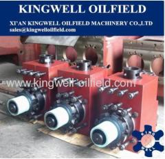
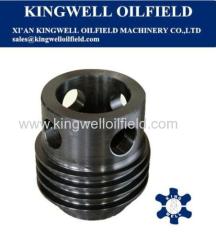
7. Hydraulic cylinder
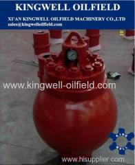
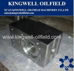
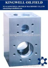
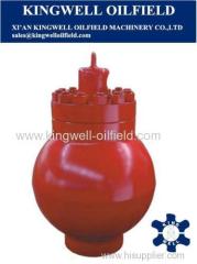
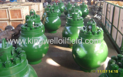
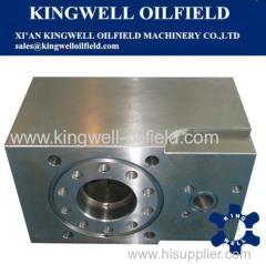
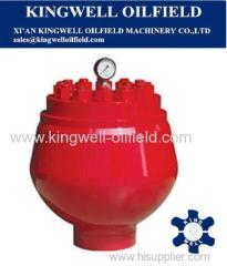
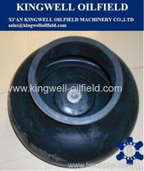
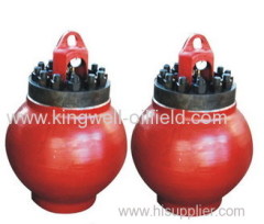
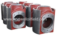
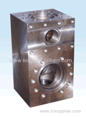
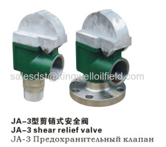
Hydraulic cylinder is forged of alloy steel. Three cylinders of one pump areinterchangeable with each other. According to customers special requirements, toenhance the anti-corrosion performance, the surface of the hydraulic cylinder issupposed to be processed with chemical plating nickel. Pulsation dampener ,shear relief valve and discharge strainer are separately mounted on the outlet.
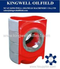
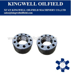
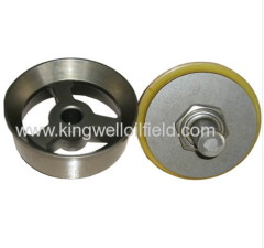
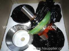
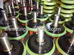
8. Valve assembly
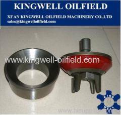
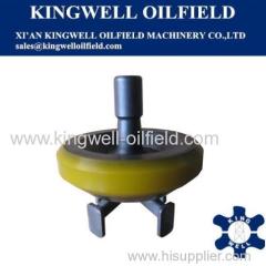
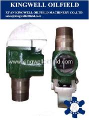
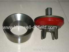
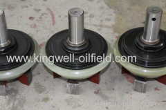
The suction valves and discharge valves of RLF mud pump are interchangeable with each other.
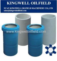
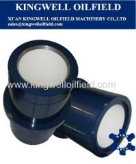
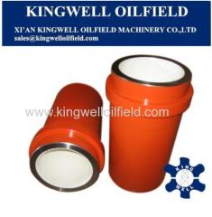
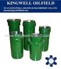
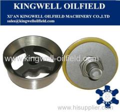
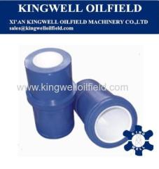
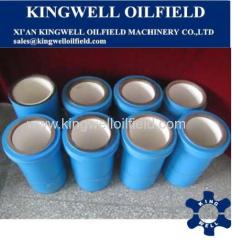
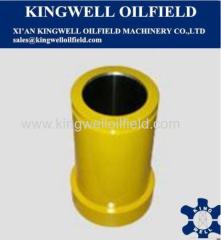
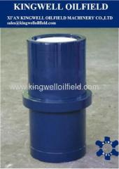
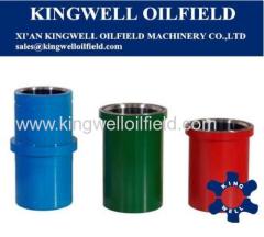
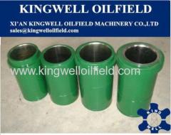
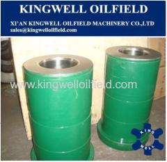
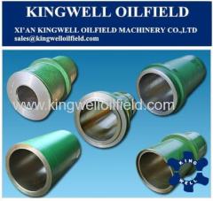
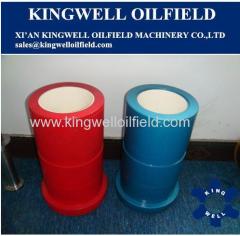
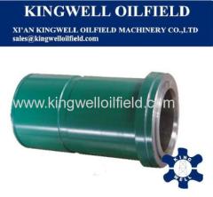
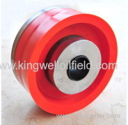
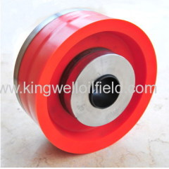
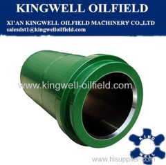
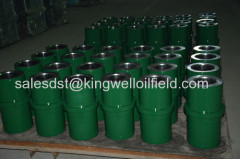
9. Liner
The suction valves and discharge valves of RLF mud pump are interchangeable with each other.
10.Spray pump
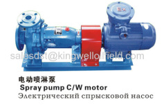
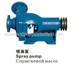
This system is consisted of spray pump, cooling water tank and spray pipelines with the function of the necessary cooling and splashing to liners and pistons toprolong their lifetime.
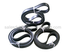
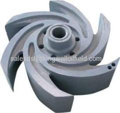
The splashing pump is the centrifugal pump which can be driven by the belt mountedon the end of input shaft, or can be individually driven by a motor with wateras the cooling and lubrication media.
To wash the interface between the pistons and liners back and forth , the fixed spray pipelines are employed which are secured inside the shell.
11.Lubrication system
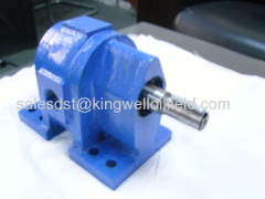
The combination of forced lubrication and splashing lubrication is used for thepower end. For the purpose of forced lubrication, the gear oil pump located at the oil tank feeds compressed oil to crossheads, extension rods and bearingsrespectively via the lubrication pipe lines. More ever, the operation situationof the gear oil pump can be observed by the manometer embedded in the after body of mud pumps.
12.Charging system
Each mud pump can be equipped with one charging pump to avoid air blocking caused bylow pressure at the suction inlet. The spray system is driven by a special motor which is installed on the suction pipe assembly. To reduce the total power supply of drilling rigs, driving shaft is employed to drive the spray pump as well.